Published
- 10 min read
Conservation of angular momentum in moving axis
Just 3 days ago, I found an interesting tweet about mechanic puzzle:
A particle is attached through a rod to a point that moves along a straight guide with constant speed v. The particle starts at rest and slides frictionless on the horizontal plane containing the guide. What is the path traced by the particle? pic.twitter.com/oWkjM6pTdh
— Luca Moroni (@sfera314)
September 7, 2021
The question seems innocent and simple. But the answer is a little bit counter intuitive. I was fascinated with the idea behind it.
So, when I read the question at a glance, my intuition said the motion should include a circular function, like a sinusoid. Since the point in the guide travels at constant speed, I jokingly guessed that the motion should look like a cycloid from an idle observer.
I immediately look at the reply first, to see how others guessed at the solution. To my surprise, the original tweet already include the answer from the author. Oops, it seems the whole thread happens 8 hours prior. It came to my feed late due to the timezone difference. Hahaha.
The author explained that the trajectory of the P particle is cycloid. Wow, I did guess right??? However some people in the replies said that the trajectory might be a tractrix. I don’t even know what tractrix is, so I immediately try to read about it in wikipedia. After looking at the tractrix’s motions, I began to wonder myself. Was it tractrix or cycloid?
The beauty of science is that you can check it yourself. In the case of mechanic puzzle like this, usually it is just enough to use the Laws of Mechanics to proof if the trajectory is correct. If it has contradiction, the trajectory will be wrong.
So, let’s have some fun with it.
Deriving the equation of motion
Without looking at the author’s answer details, I tried to deduce the equation of motion myself. The approach is a little bit different with how the author proposes (using a change of frame/perspectives). This is not because I don’t believe the author’s answer. It’s more because, I’m not a physicist myself, so there’s a huge chance that my initial intuition is wrong. So, I should use a proper step by step reasoning to see where I could go wrong.
Initially, I want to start by using a Lagrangian, but since the trajectory itself is unknown, it’s probably useless. No potential energy either, so whatever happens with the equation of motion will most probably contains constraint Force. If it does uses constraint Force, then let’s just use Newton’s Law directly.
Before we use Newton’s Law, we establish what is the current inertial reference frame. By the problem statement, we have two. First, is the idle observer (us). Second, is the point moving with constant velocity along the straight beam. The second is an inertial frame because the point doesn’t change in speed magnitude and direction. If you put the second observer here, they will observe the same forces as us, the idle observer.
We will start with arbitrary time . In this setup, let’s say that at time we have arrangements like this:
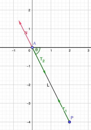
The particle is displaced with angle of . Particle is our point that travels along the straight beam. The rod connecting and is considered rigid. Thus the distance between them is always the same: .
There are 3 forces at play. Both and are action-reaction pairs, which corresponds to a force tension in the rod. The third force is a force that acts as a counter-force or balancer, namely . This force mainly act to negate the force , so that point doesn’t have a net force (because it travels in a constant speed). Basically, it is coming from the Newton’s First Law.
To make it simpler, let’s just compose all the forces. Let say that both particle and have the same mass. The center of mass should be in the middle of the rod, so the distance from is .
This assumption can also be used for arbitrary mass ratio between and , but for demo purposes, let’s just say both have the same mass for now.
For center of mass analysis, all internal forces (action-reaction) will cancel out each other. This will leave out only force .
We have an interesting conclusions here. The negating force is directly proportional to the magnitude and direction of particle ‘s acceleration. However, remember that ‘s acceleration vector must point to the same direction of force , because that’s the only force affecting . We now conclude that both and have the same direction as the direction between point to , because that’s the direction of the rod’s length.
This condition is unique. Even though accelerate towards point , but their distance can’t be less than L, due to the rigid rod. That means, the only possible movement can have, is a circular motion around , with the corresponds to it’s centripetal acceleration. We now have:
We must first define the circular radius. So we have to find the axis first. However, Newton’s Law for circular motion only works the same in an inertial reference frame. Since the whole span of the rod experienced acceleration, the axis can only be in point . We can only use the inertial reference frame in . Thus . Meanwhile, the angular speed is equal to the rate of change of the angle , which means .
For regular circular motion, the magnitude of (centripetal acceleration) is constant. The speed of the particle is also constant. But the direction changes following the usual circular motion. If we define to be the angle that points to positive x-axis, and increase clockwise (so that is positive values), we got the following formula:
Note that the signs in the formula above was set so that the direction match.
We called it because it is a tangential speed of the circular motion. Remember that here is defined as observed by point . That means, the velocity of point as observed by us, the idle observer, is:
Substitute the fact that in circular motion: with certain choice of initial angle.
From the velocity definition above, we can integrate to have position vector of as described by time parameter . This is our trajectory. The integration is easy because any other variables except are constants.
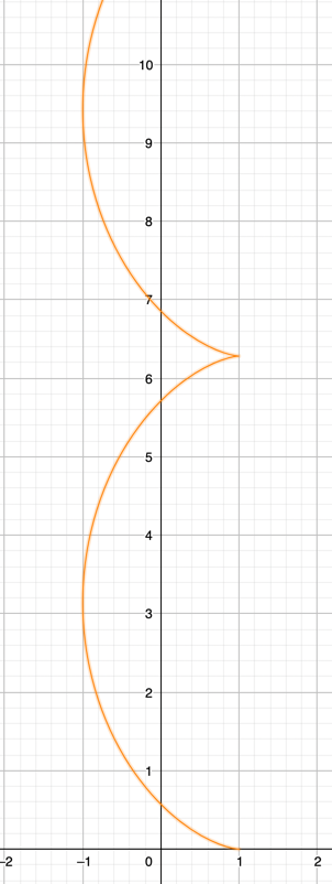
Let us now compare if it is indeed a cycloid. If we look at the cycloid trajectory definition from Wikipedia, we need to swap x and y, because our cycloid is drawn vertically. I also need to do some coordinate transform to match with the previous case. The cycloid equation is:
It kind of looks like this, if we assume :
Take the derivative, to get the velocity equation:
As you can see (just match it out yourself), if we use the same initial angle and same radius to , then we have the same velocity described by the previous equation of motion. Well, not exactly the same. The following condition has to be the same:
We don’t know yet that it must hold. As far as we know currently, the equation of motion (from Newton’s Law earlier) doesn’t specify any relation between and . That means can be arbitrary, and it will still satisfy the same equation of motion. The only requirement is just needs to be constant.
Checking the initial condition
Because, it can be arbitrary, let’s just check if the initial condition corresponds to a certain value.
If I understand it correctly, this is actually the whole point of the tweet above. The author basically saying, the equation of motion can be deduced just from the initial condition (and the constraints), due to a change of frame.
At , we (the idle observer) observe that is zero while the point moved with speed . If we have a change of frame into observer , we see point have equal speed to but with opposite direction. Observer sees moving in a circular motion, because the force acting on is always perpendicular from direction. The length of the rod can’t change either. So definitely undergone circular motion with axis in (currently non moving).
It has to.
It just follows immediately that . This will cause the trajectory of from our perspectives to become cycloid, due to the equation of motion we established before.
Can it be a non-cycloid?
Our equation of motion is already restrictive enough. A variation of the motion can only happen if value is different. Let’s just suppose in our drawing above, it corresponds to where the as observed by us. That means, point have initial angle from the x-axis. This means, if we observe it from frame, we notice that the rod and the velocity is not perpendicular, and this is a trouble for me.
First, our initial equation of motion does not consider radial speed at all. However from frame, we can see that have both tangential and radial component, with the radial velocity pointing outward the circle.
How to resolve this inconsistencies? Frankly, I am not sure. The force acting on is still along the span of the rod, pointing inward. I can be wrong, though. My interpretation is that it is not possible for to have radial component velocity, because that would mean the length of the rod will change. But, if we accept that will only have tangential component, that means we can’t calculate this speed just by using translational relativity like before.
In summary, previously have speed with equal magnitude but opposite direction observed by because linear momentum conservation applies in y-axis (no y-direction force). We can’t do so in this particular case, because both x and y axis does not have linear momentum conserved on initial condition. That is the possible physical explanation.
For people that prefer to infer by math, the set of possible initial condition was actually restricted by the integration.
From the motion equation here:
You can extract that the velocity of must be zero at some point, because the initial condition for P stated in the tweet was: it is started at rest.
It can only be zero when the x velocity is zero, which is when or .
But, from those two values, only that can cause the y velocity to be zero, .
So, the math said, there is no other way. The path can only be a cycloid given the initial condition stated in the tweet.
In what condition that the path becomes tractrix?
This can be a topic for another day. But so far, the constraint was just that all the forces involved in has to act along the rod. If only can have additional force factor, for example friction in the ground, it can have a force that is not with the direction of the rod. This is the only way that the equation of motion can be reanalyzed.